


MOXA ICF-1280I
2-port industrial PROFIBUS-to-fiber converters

 Eigenschaften
 Beschreibung
 Weitere Informationen
 Ähnliche Produkte
 Seite drucken
 Preis anfragen
 zeige Notizliste
 PDF
PDF
 Eigenschaften
 Beschreibung
 Weitere Informationen
 PDF
PDF
- Redundant fiber ring with zero recovery time
- Examine network-wide fiber communication from a single converter
- Auto baudrate detection and data speed up to 12 Mbps
- PROFIBUS bus fail prevents corrupted datagram in functioning segment
- Alarm by relay output
- 2 kV galvanic isolation protection
- Dual power inputs for redundancy
- Extends PROFIBUS transmission distance up to 45 km
- Wide temperature model available for -40 to 75°C environments
- Supports Fiber Signal Intensity Diagnosis
Die industriellen PROFIBUS-zu-Glasfaser-Konverter der Serie ICF-1280I werden zum Umwandeln von PROFIBUS-Signalen von Kupferkabel zu Glasfaser eingesetzt. Sie können die überbrückbaren Strecken für die serielle Übertragung um bis zu 4 km (Multimode-Glasfaser) oder um bis zu 45 km (Single-Mode-Glasfaser) erhöhen. Der ICF-1280I bietet einen Überspannungsschutz bis 2 kV für das PROFIBUS-System und verfügt über zwei Betriebsspannungseingänge, die den unterbrechungsfreien Betrieb Ihres PROFIBUS-Geräts gewährleisten.
Remote Fiber Diagnosis
Optical fiber cables are often deployed for long distance communication and a fiber optic inspection pen is used by engineers to ensure proper communication quality of the fiber cable. The ICF-1280I series converters eliminate the need for a fiber optic inspection pen by providing a Remote Fiber Diagnosis function that uses DIP switch adjustments. There are two major functions provided by Remote Fiber Diagnosis: (1) determining which side (Tx or Rx) is causing the problem on the converter; (2) examining the fiber connections for the overall topology from any individual converter. Fiber cable abnormalities can be automatically detected and identified by the LED indicator even if it is not adjacent to the converter. Remote Fiber Diagnosis facilitates fiber cable deployment and management, and also significantly shortens troubleshooting time by examining fiber connections for the overall topology from any individual converter.
Redundant Ring
The ICF-1280I series converters can connect PROFIBUS devices in a redundant fiber ring topology. Use the DIP switch to configure all the ICF- 1280I converters to Redundant Ring mode. When a PROFIBUS master transmits a signal from one converter to the PROFIBUS slave devices, this signal will travel to all the converters around the ring until it returns to the original converter and terminate. The redundant ring structure ensures no packet loss with zero recovery time.
PROFIBUS Fail Safe
Electrical noise may be generated when a PROFIBUS device malfunctions or the serial interface fails, resulting in bus failure. Traditional media converters transmit noise signals through the fiber wire to the other converter. This not only disrupts data communication between the two buses, but will also bring communication across the entire system to a halt. When this occurs, the engineers will not be able to easily locate the failed device because the entire PROFIBUS network is down. To avoid this situation, the ICF-1280I series converter has a mechanism to detect and recognize noise signals. If the bus fails on one side, the noise signal will not propagate through the ICF-1280I converter and affect additional bus segments. In addition, the ICF-1280I converter will also trigger an alarm to provide the location of the failure to the field engineer.
Fiber Signal Intensity Diagnosis
In some circumstances, you may need to measure the receive level of the fiber optic port with a voltmeter, which can be connected while the device is operating (doing so will not affect data transmission). The measurement can be taken with a voltmeter and read on a PLC that uses floating high impedance analog inputs, which allows you to do the following: 1. Record the incoming optical power for later measurement (e.g., to indicate aging or damage). 2. Carry out a good/bad test (limit value).
Technology
Interface
PROFIBUS Communication
Physical Characteristics
Environmental Limits
Power Requirements
Standards and Certifications
Ordering Information
Optical fiber cables are often deployed for long distance communication and a fiber optic inspection pen is used by engineers to ensure proper communication quality of the fiber cable. The ICF-1280I series converters eliminate the need for a fiber optic inspection pen by providing a Remote Fiber Diagnosis function that uses DIP switch adjustments. There are two major functions provided by Remote Fiber Diagnosis: (1) determining which side (Tx or Rx) is causing the problem on the converter; (2) examining the fiber connections for the overall topology from any individual converter. Fiber cable abnormalities can be automatically detected and identified by the LED indicator even if it is not adjacent to the converter. Remote Fiber Diagnosis facilitates fiber cable deployment and management, and also significantly shortens troubleshooting time by examining fiber connections for the overall topology from any individual converter.
Redundant Ring
The ICF-1280I series converters can connect PROFIBUS devices in a redundant fiber ring topology. Use the DIP switch to configure all the ICF- 1280I converters to Redundant Ring mode. When a PROFIBUS master transmits a signal from one converter to the PROFIBUS slave devices, this signal will travel to all the converters around the ring until it returns to the original converter and terminate. The redundant ring structure ensures no packet loss with zero recovery time.
PROFIBUS Fail Safe
Electrical noise may be generated when a PROFIBUS device malfunctions or the serial interface fails, resulting in bus failure. Traditional media converters transmit noise signals through the fiber wire to the other converter. This not only disrupts data communication between the two buses, but will also bring communication across the entire system to a halt. When this occurs, the engineers will not be able to easily locate the failed device because the entire PROFIBUS network is down. To avoid this situation, the ICF-1280I series converter has a mechanism to detect and recognize noise signals. If the bus fails on one side, the noise signal will not propagate through the ICF-1280I converter and affect additional bus segments. In addition, the ICF-1280I converter will also trigger an alarm to provide the location of the failure to the field engineer.
Fiber Signal Intensity Diagnosis
In some circumstances, you may need to measure the receive level of the fiber optic port with a voltmeter, which can be connected while the device is operating (doing so will not affect data transmission). The measurement can be taken with a voltmeter and read on a PLC that uses floating high impedance analog inputs, which allows you to do the following: 1. Record the incoming optical power for later measurement (e.g., to indicate aging or damage). 2. Carry out a good/bad test (limit value).
Technology
- Standards
IEC 61158-2 for PROFIBUS DP
Interface
- P1/P2 Port
ST optical fiber
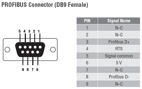
P3 Port
PROFIBUS DP (DB9 female)
Relay Alarm
One relay output with current carrying capacity of 2 A @ 30 VDC (Normal open)
LED Indicators
PWR1, PWR2, Ready, P1, P2, P3, Fault
DIP Switches
DIP 1 to 4: Baudrate setting
DIP 5: Fiber link monitor
DIP 6 to 7: Linear/Star mode (w/ optional P1/P2 disable), Redundant Ring mode
DIP 8: Remote Fiber Diagnosis
PROFIBUS Communication
- Data Rate
9.6, 19.2, 45.45, 93.75, 187.5, 500, 1500, 3000, 6000, and 12000 Kbps
Auto Baudrate
Yes
Isolation Protection
2 kV
Physical Characteristics
- Housing
Metal
Mounting
DIN-Rail mounting, wall mounting (with optional kit)
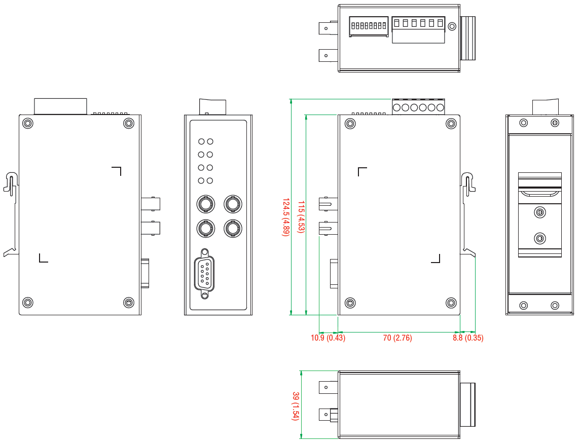
Dimensions
39 x 115 x 70 mm (1.54 x 4.53 x 2.76 in)
Weight
225 g
Environmental Limits
- Operating Temperature
Standard Models: 0 to 60°C (32 to 140°F)
Wide Temp. Models: -40 to 75°C (-40 to 167°F)
Storage Temperature
-40 to 75°C (-40 to 167°F)
Ambient Relative Humidity
5 to 95% (non-condensing)
Power Requirements
- Input Voltage
12 to 48 VDC
Power Consumption
315 mA @ 12 V
Connector
Terminal Block
Power Line Protection
Level 3 (2 kV) Surge Protection
Over Current Protection
1.1 A
Standards and Certifications
- Safety
UL 508, EN 60950-1
Hazardous Location
UL/cUL Class I Division 2 Groups A/B/C/D, ATEX Zone 2 EEx nC IIC, IECEx
EMC
CE, FCC Part 15 Subpart B Class A
EMI
EN 55022, Class A; EN 55024
EMS
EN 61000-4-2 (ESD) Level 3,
EN 61000-4-3 (RS) Level 3,
EN 61000-4-4 (EFT) Level 3,
EN 61000-4-5 (Power Surge) Level 3,
EN 61000-4-5 (Communication Surge) Level 3,
EN 61000-4-6 (CS) Level 3
Green Product
RoHS, CRoHS, WEEE
Freefall
IEC 60068-2-32
Ordering Information
| Available Modules | |
| ICF-1280I-M-ST | PROFIBUS to fiber converter, multi-mode, 2 ST connector, 0 to 60°C |
| ICF-1280I-S-ST | PROFIBUS to fiber converter, single-mode, 2 ST connector, 0 to 60°C |
| ICF-1280I-M-ST-T | PROFIBUS to fiber converter, multi-mode, 2 ST connector, -40 to 75°C |
| ICF-1280I-S-ST-T | PROFIBUS to fiber converter, single-mode, 2 ST connector, -40 to 75°C |
 Kunden, die diesen Artikel gesehen haben, sahen auch